

Blog
Mini Case Study: Verifying the Performance of a Central Ventilation System in an Apartment

What Does Verifying the Performance of a Central Ventilation System Involve?
The verification process begins with a review of the engineering calculations and system design. Next, the team inspects the installation and checks whether all installed components comply with the design documentation.
The team then commissions the system and checks the functionality of all components. After that, airflow rates are balanced and the achieved airflow is measured. Finally, key indoor air quality parameters are verified.
To explain this process more clearly, the following sections describe the installed system, its design constraints, and the specific engineering challenges.
In an approximately 200 m² apartment in Belgrade, Marquis Intelligence designed and implemented a central ventilation system with a high-efficiency heat recovery unit.
To meet the client’s demanding requirements, Marquis Intelligence added a dedicated filtration chamber, a bipolar ionization system, and a steam humidifier.
Architecture as a Limiting Factor in Ventilation System Design
This project shows how strongly building architecture can influence the selection, configuration, and long-term performance of a ventilation system.
Building Location and Apartment Position
The apartment is located in an existing multi-storey building with a glass façade. The building has an Energy Performance Class A rating.
From the earliest design stages, Marquis Intelligence had to adapt the ventilation system to the existing architecture, available installation space, and other building services.
A Glass Façade as a Constraint on Ventilation System Selection
At the beginning of the project, Marquis Intelligence evaluated both centralized and decentralized ventilation concepts.
The glass façade ruled out individual façade penetrations for the outdoor air intake and exhaust required by decentralized ventilation units. For that reason, the team rejected decentralized ventilation as technically infeasible.
Marquis Intelligence therefore selected a central ventilation system with a radial duct distribution network serving each room independently.
Even then, the façade could not accommodate either the outdoor air intake or the exhaust air discharge. The team therefore designed separate intake and exhaust routes.
Fresh outdoor air enters from the roof terrace. The team had to consider the location of other rooftop installations, especially existing kitchen and sanitary exhaust systems connected to the building’s vertical shafts.
The design also had to account for the shaft carrying fresh air from the roof to the apartment several floors below.
These constraints made both the engineering design and the subsequent performance verification particularly demanding.
SEE ALSO: Decentralized Home Ventilation Systems: Advantages and Limitations
Interior Design as a Design and Installation Constraint
The apartment’s interior design significantly influenced how the central ventilation system could be installed.
The first major decision concerned the location of the heat recovery unit. The team then determined the position of the humidifier, the outdoor air intake, the exhaust air discharge, and the duct routes.
Suspended ceilings were available only above the entrance areas of the rooms. This constraint led to the use of supply grilles utilizing the Coandă effect.
The ductwork had to fit within the available ceiling voids without compromising the interior design or requiring unnecessarily invasive construction work. Construction works themselves were outside the contractual scope of Marquis Intelligence.
Protecting the existing interior during installation was equally important. This included the elevator and common corridors, as well as the apartment’s flooring, furniture, and other interior finishes.
Ventilation Design Calculations
Marquis Intelligence designed the ventilation system in accordance with DIN 1946-6. The calculations covered minimum ventilation for moisture protection, reduced ventilation, nominal ventilation, and intensive ventilation.
The manufacturer’s design software calculated a nominal airflow of 184 m³/h and an intensive airflow of 239 m³/h. However, calculations alone cannot replace professional judgment about the specific characteristics of each project.
For that reason, the final design used a ventilation unit with a higher capacity than the calculated minimum requirement.
The team determined airflow rates according to the intended use of each room and balanced them across the apartment. Fresh air enters the bedrooms and dining area. Extract air leaves through the kitchen, bathrooms, and other spaces with higher moisture and odor loads.
The team also coordinated the ventilation system with the apartment’s air-conditioning system.
Airflow balancing takes place centrally through balancing valves on the supply and extract manifolds. This is one of the key advantages of the installed system.
Heat Recovery
The central ventilation unit uses a high-efficiency counterflow plate heat exchanger.
Supply and exhaust air pass through separate channels and do not mix. Heat transfers through the heat exchanger surfaces from one air stream to the other.
SEE ALSO: Plate or Rotary Heat Recovery Units in Residental Central Ventilation?
The ventilation system provides the required quantity and quality of fresh air, while indoor temperature is maintained by the heating and cooling systems.
Air Treatment
Marquis Intelligence installed a dedicated filtration chamber upstream of the central ventilation unit. It contains a HEPA H14 filter and a molecular filter.
The HEPA H14 filter captures extremely fine airborne particles. The molecular filter reduces certain gaseous pollutants and unpleasant odors.
High-efficiency filtration also increases airflow resistance and pressure drop. For that reason, the team had to verify the available fan static pressure and assess the filtration chamber’s effect on the overall airflow.
A bipolar ionization system provides an additional stage of air treatment. It operates on the principle of dielectric barrier discharge (DBD). The ionization unit is installed in the supply air plenum immediately upstream of the distribution manifold. From there, the system distributes ionized air throughout the apartment.
The system also includes a steam humidifier, in accordance with the client’s requirements and needs.
During commissioning, the team found that the water downstream of the building’s central water treatment system had insufficient electrical conductivity for stable humidifier operation.
The humidifier water supply was therefore reconnected directly to the municipal water main. Measurements confirmed that the water conductivity met the manufacturer’s requirements for reliable operation.
This detail shows why a central ventilation system cannot be designed in isolation from other building services.
Existing Local Exhaust Systems and the Central Ventilation System
The kitchen range hood operates independently of the central ventilation system.
It operates intermittently and at airflow rates significantly higher than those required for continuous apartment ventilation. The existing bathroom exhaust fans also remained in operation. At the same time, the central ventilation system has its own dedicated extract points.
This arrangement separates three functions: continuous ventilation of the apartment, intermittent boosted exhaust from the bathrooms, and separate extraction of cooking vapors and kitchen emissions.
Internal and External System Verification
The design and installation passed through several levels of professional review.
A Mechanical Engineer prepared the ventilation calculations. A licensed consulting engineer then reviewed the engineering design and technical documentation.
The project parameters were also submitted to the equipment manufacturer. The manufacturer processed them using its centralized engineering software in Germany.
This review covered total and individual airflow rates, supply and extract air distribution, ventilation unit selection, and compatibility with the manufacturer’s technical requirements.
After installation, Marquis Intelligence submitted photographic documentation of the completed system to the manufacturer. The manufacturer then reviewed the equipment positioning, component interconnections, and key installation details.
The verification process therefore included engineering calculations, review by a licensed engineer, technical verification by the equipment manufacturer, and inspection of the completed installation.
Airflow Verification
Following system commissioning, the team measured airflow at the intake grille of the ventilation chamber. During the measurement, the heat recovery unit operated in Boost Mode.
The team used professional airflow measurement equipment. They divided the grille surface into six equal measuring zones and took measurements at three points within each zone.
After applying a 5% correction factor for possible external influences, the corrected airflow rate was 428 m³/h.
The measurement confirmed the airflow achieved at the intake side of the ventilation chamber in Boost Mode with clean filters.
Virtually Silent Operation
Supplying the required quantity of fresh air is not enough to ensure a high-quality ventilation system. Air distribution within the occupied spaces is equally important.
In this apartment, the system operates virtually silently. Occupants do not perceive noticeable airflow.
This result depends on proper duct sizing, appropriate air velocities, a sufficient number of supply terminals, correct terminal positioning, and precise system balancing.
Independent Indoor Air Quality Measurements
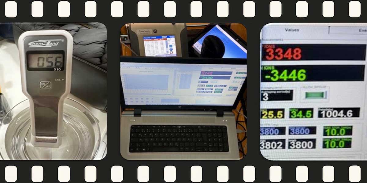
After approximately 24 hours of continuous system operation, with all windows kept closed, an independent scientific institute carried out instrumental measurements of the apartment’s indoor air quality.
Using professional monitoring equipment, the following indoor air quality parameters were recorded:
- CO₂: 668–889 ppm
- TVOC: 207–246 ppb
- Formaldehyde: 16 ppb
- Fewer than 50 particles/cm³ within the measured particle size range of 0.3–10 µm
- Ozone (O₃), sulfur dioxide (SO₂), and nitrogen dioxide (NO₂): not detected
CO₂ concentrations remained within an appropriate range even in rooms occupied by considerably more people than assumed in the original design calculations. For example, a home office designed for one occupant was occupied by four people during part of the testing period, yet the measured CO₂ concentration reached only 889 ppm.
SEE ALSO: CO₂ in Your Home – Is It There and Where Does It Actually Come From?
No measurable concentration of ozone was detected during system operation.
A particle concentration of less than 50 particles/cm³ corresponds to very clean indoor air, according to the classification applied in the laboratory report. It should be noted that this result refers to the instrument’s measurement range of 0.3–10 µm.
The report further states that the combined effect of ventilation, filtration, and bipolar ionization would be expected to become even more pronounced under conditions of poorer outdoor air quality.
What Does This Project Demonstrate?
This project shows that a central ventilation system can also be retrofitted into an apartment in an existing multi-storey residential building. However, the building must provide suitable spatial and technical conditions.
Such a solution involves far more than installing a central ventilation unit.
The configuration and total cost of the system depend on the building itself and the client’s requirements. Other important factors include the required airflow, the level of air treatment, duct routing, the locations of the outdoor air intake and exhaust air discharge, installation conditions, and additional system components.
SEE ALSO: Residential Ventilation by Marquis Intelligence
SEE ALSO: FAQ – Home Ventilation
What Determines the Price of a Central Ventilation System?
The price of a heat recovery unit is not the same as the cost of a complete ventilation system.
A fully engineered solution includes much more than the equipment itself. It also includes engineering calculations, system design, ductwork, installation, airflow balancing, commissioning, and performance verification.
One of the most important aspects of this project is that the team did not evaluate the result solely on the basis of the installed equipment.
The verification covered the engineering design, system configuration, completed installation, achieved airflow, and key indoor air quality parameters.
Verifying the performance of a central ventilation system is the final and indispensable stage of project implementation. It confirms whether the completed system operates in accordance with the engineering design requirements.
Long-term reliable operation also depends on regular maintenance. The best continuity is achieved when the company that designed, installed, and commissioned the system continues to maintain it in accordance with the manufacturer’s recommendations and actual operating conditions.
This article is part of the Marquis Intelligence “Mini Case Studies” series.
Document ID: MI-MCS-09.3Q-26
Document Title: Mini Case Study: Verifying the Performance of a Central Ventilation System in an Apartment
